Basic Concepts of Instrumentation and Controls for Oil & Gas Sector
In part one of this instrumentation and control (I & C) series, we'll go over the fundamental terminology and concepts used when working with industrial plants.
This is the first of a series of technical articles about instrumentation and control. In this series, we will discuss the basic concepts and principles that govern the operation of industrial plants. Concepts associated with measurements of flow, level, temperature and pressure, electronics and pneumatics instrumentation, control loops, PID control, and others will be addressed.
Article Scope
Someone once asked a colleague what his occupation was. He replied without hesitation, "I am an instrumentation and control engineer." "And what is that?" asked his interlocutor. "...Oh. Oh ... I'm in trouble," thought the engineer.
To explain what a mechanical, electrical, chemical, or electrical engineer does is relatively easy, but it is another story to concisely describe the work performed by an engineer who specializes in instrumentation and control.
Instrumentation and control are interdisciplinary fields. They require knowledge of chemistry, mechanics, electricity and magnetism, electronics, microcontrollers and microprocessors, software languages, process control, and even more such as the principles of pneumatics and hydraulics and communications.
This is what makes instrumentation and control so interesting and instructive.
In this article and the next, I will give a complete overview of the basic principles of instrumentation and control (I & C) used for the functioning and operation of industrial plants such as those involving oil and gas, pulp and paper, sugar, pharmaceutical products, food, and chemicals.
First, we'll need to cover how to measure, and to measure we need a measurement instrument.
What is a measurement instrument?
A measurement instrument is a device capable of detecting change, physical or otherwise, in a particular process. It then converts these physical changes into some form of information understandable by the user.
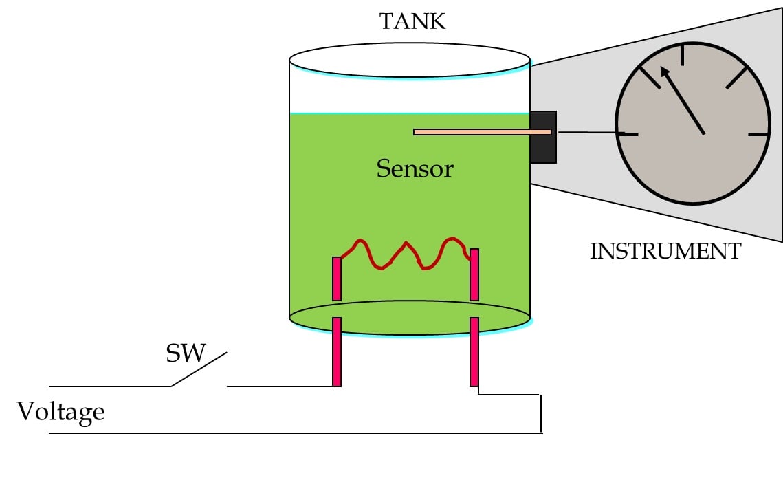
Consider the example of Figure 1.

Figure 1: An example of a measurement instrument
When the switch is closed, the resistor generates heat, increasing the temperature of the liquid in the tank. This increase is detected by the measurement instrument and shown on the scale of that instrument.
We can get the information on the physical changes in a process using direct indication or a recorder.
Indication
This is the simplest form of measurement; it allows us to know the current state of the variable.

Figure 2: Monitoring a variable via indication
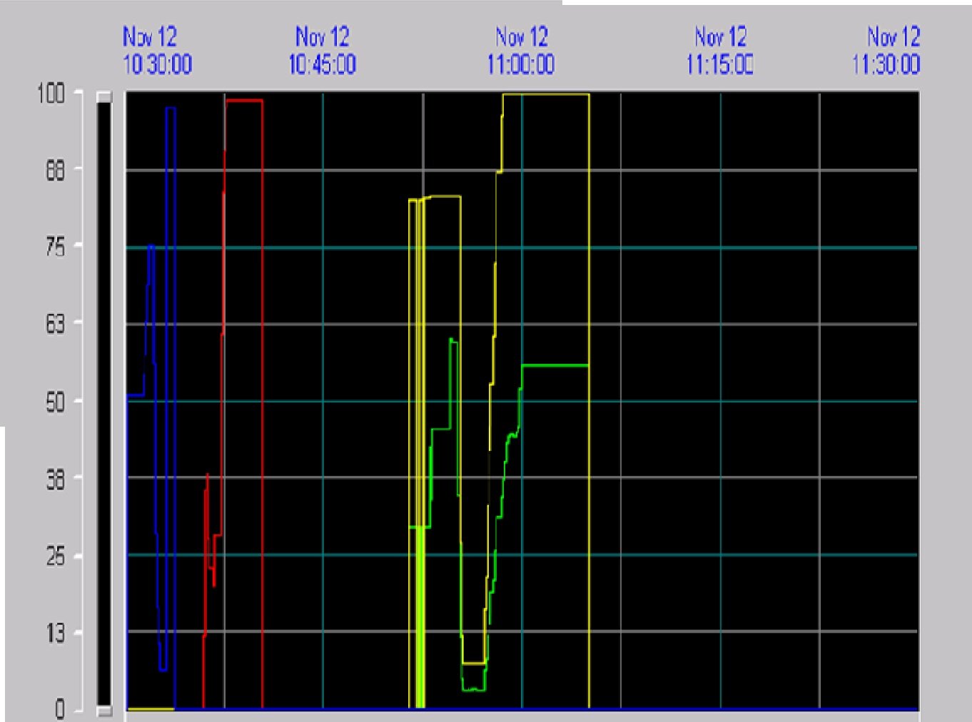
Recorder
A device that can store data allows us to observe the current state of the variable and how it behaved in the past. A recorder provides us with the history of the variable.

Figure 3: A display showing how measurements have changed over time
Elements of a Measurement Instrument
Measurement instruments consist primarily of the following parts:
- Sensor: This element is a device that experiences changes in its physical properties as a result of changes in the process it's measuring.
- Amplifier / Conditioner: Changes detected by the sensor may be very small, so they must be amplified and then conditioned such that they can be properly displayed.
- Display: The measured data should be presented in an understandable way. This can be done using a graduated instrument or an electronic display. Sometimes the display additionally acts as a recorder in order to convey the measurement's history or trends.

Figure 4: Elements of a measurement instrument
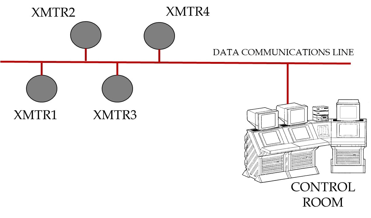
Usually, the measurement information generated by an instrument must be sent to a control center (or control room) that is physically distant from the instrument. In general, this information must conform to established specifications.

Figure 5: Measurement information is sent from the instrument to the control room
When an instrument has the ability to send information, we call it a transmitter (XMTR).
Classification of Instruments
There are different classifications for measurement instruments. We can classify them, for example, as in-field instruments or panel instruments. The in-field instrument is installed close to the process or measuring point. It must be physically robust if it will be exposed to harsh environmental conditions. Panel instruments are in a controlled-environment room (often a clean space with air conditioning and controlled humidity).
Another classification is pneumatic instruments vs. electrical/electronic instruments.
Pneumatic Instruments
As the name suggests, these are devices that are powered by air.
One of the advantages of these instruments is that they do not consume electricity, so they can be used in areas where it would be dangerous or inconvenient to use electrical power. They work with a single variable, are imprecise instruments, are affected by vibrations and temperature changes, and have high maintenance requirements. The output signal of the transmitters is between 3 and 15 psi, and the maximum transmission distance is approximately 200 meters.

Figure 6: Basic diagram of a pneumatic instrument
Electrical / Electronic Instruments
Electronic instruments can be divided into three general categories: analog, smart analog, and digital.
Analog:
- Output signal: 4 - 20 mA
- Transmission distance: 1200 m (typical)
- Data for one variable is transmitted
- Good accuracy
- Easy maintenance

Figure 7: Basic diagram of an electronic instrument (XMTR)
Smart Analog:
- Characterization of the sensor as measuring temperature, static pressure, etc.
- Excellent accuracy
- Self-diagnosis (i.e., the sensor can analyze problems in its own functionality)
- One variable
Digital:
- Multiple instruments can use a single cable
- Transmission of multiple values for each instrument (process variables, calibration, diagnostics, range)
- Distance: approximately 1900 m without a repeater
- Data capacity is influenced by the mode of transmission (cable, fiber optic, wireless)

Figure 8: Digital transmitters
General Concepts
Range: The region between the limits within which a variable is measured. It indicates the minimum and maximum values that limit the region. The range is expressed with two numbers, e.g., 10 to 20 °C, 10 to 150 V, 0 to 100%
Span: Calculated as the maximum value of the range minus the minimum value of the range. Span is expressed with a single number in process units, e.g., 120 °C, 30 V, 150 liters per second.
Elevation: If the lower limit of the range is a positive value, this lower limit is the elevation. Example: If the range is 50 °C to 200 °C, we can say that the elevation is 50 °C or 33.3% of the span.
Depression (also referred to as suppression): If the lower limit of the range is negative, the absolute value of this lower limit is the depression. Example: If the range is -10 °C to 80 °C, we can say that the depression is 10 °C or 11.1% of the span.
Overrange: When a device is calibrated to operate within a certain range but may be subjected to values above or below that range, then it requires a protection mechanism to prevent damage to the instrument or to prevent the indicator from exceeding its upper or lower limit. When the measured values are above the maximum value, we have positive overrange. When the measured values are below the minimum value, we have negative overrange.

Figure 9: Examples of range, span, elevation, and depression
Error: The difference between the measured value and the actual (or expected, or desired) value of a physical variable. The error can be positive or negative. When the measured value is greater than the actual value, the error is positive. When the measured value is less than the actual value, the error is negative.
If measured > actual, error > 0
If measured < actual, error < 0
The error can be expressed
- in engineering units (e.g., °C, psi)
- as a percentage of the span (e.g., +/- 3% of the span)
- as a percentage of the measurement (e.g., +/- 5% of the measurement)
Reference value: In a general sense, this refers to the actual, expected, or desired value of a variable. In the context of a feedback control system, the measured value is fed back and subracted from the reference value in order to generate the error signal.
Accuracy: A number that defines the limits of the error. When we say that an instrument has an accuracy of 0.1% of the span, this means that anywhere within the range, the readings do not differ from the actual value by more than 0.1% of the span.
An Example
For a better understanding of the concepts expressed above, consider the following example.
We have an oil tank where we are required to continuously measure the temperature. The operating conditions for this process are as follows:
- Minimum temperature: -10 °C
- Maximum temperature: 90 °C
- The measurement accuracy must be 1% of the span or better
- The temperature measurement must be displayed locally and remotely

Figure 10: Our example system
First, we must select a measuring instrument that allows us to measure the temperature of the liquid in the tank. Since the information should be available locally and remotely, we will choose a temperature transmitter.
This transmitter must have the following characteristics:
- Range: -10 °C to 90 °C
- Span: 90 °C - (-10 °C) = 100 °C
- Depression: 10 °C or 10% of the span
- Accuracy: 1% of the span = 1% × 100 °C = 1 °C
- This accuracy of 1% ensures that, in each measurement or temperature reading, variation or errors will not exceed +/- 1 °C
On an additional note, we must ensure a proper relationship between the range and the standardized transmitter output. To calibrate the instrument, we must associate the minimum value of the range (-10 °C) with the minimum value of the output (4 mA) and the maximum value of the range (90 °C) with the maximum value of the output (20 mA).
Conclusion
In this article we have discussed measurement devices and fundamental measurement concepts in the context of instrumentation and control systems. We also looked at a simple example system involving a heating element and an instrument that can collect and transmit temperature data. In the next article, we will cover the four basic variables used in industrial applications: flow, level, temperature, and pressure. Also, we will discuss various sensors such as orifice plates, thermocouples, and RTDs, and we will review instruments and transmitters used for measuring these four physical variables.
Comments
Post a Comment